SAF™ 2507 is a super-duplex (austenitic-ferritic) stainless steel for service in highly corrosive conditions. The grade is characterized by:
- Excellent resistance to stress corrosion cracking (SCC) in chloride-bearing environments
- Excellent resistance to pitting and crevice corrosion
- High resistance to general corrosion
- Very high mechanical strength
- Physical properties that offer design advantages
- High resistance to erosion corrosion and corrosion fatigue
- Good weldability
Standards
- UNS: S32750
- EN Number: 1.4410
- EN Name: X 2 CrNiMoN 25-7-4
- SS: 2328
Product standards
- Seamless tube and pipe: EN 10216-5
- Seamless and welded tube and pipe: ASTM A789; A790
- Flanges: ASTM A182
- Fittings: ASTM A182; (ASTM A815 applied for)
- Plate, sheet and strip: ASTM A240, EN 10088-2
- Bar steel: ASTM A479, EN 10088-3
- Forged billets: EN 10088-3
Approvals
- Approved by the American Society of Mechanical Engineers (ASME) for use in accordance with ASME Boiler and Pressure Vessel Code, Section VIII, div. 1. There is no approval for UNS S32750 in the form of plate. However, according to ASME paragraph UG-15, the design values for seamless tube according to ASME Section VIII, div. 1 are also allowed to be used for plate.
- ASME B31.3 Chemical Plant and Petroleum Refinery piping
- VdTÜV-Werkstoffblatt 508
- NACE MR0175/ISO 15156 (Petroleum and natural gas industries - Materials for use in H2S-containing Environments in oil and gas production - Part 3: Cracking-resistant CRAs (corrosion resistant alloys and other alloys) (Published:2015)
Chemical composition (nominal)
| C | Si | Mn | P | S | Cr | Ni | Mo | N |
|---|---|---|---|---|---|---|---|---|
| ≤0.030 | ≤0.8 | ≤1.2 | ≤0.025 | ≤0.015 | 25 | 7 | 4 | 0.3 |
Corrosion resistance
General corrosion
SAF 2507™ is highly resistant to corrosion by organic acids, e.g. experience less than 0.05 mm/year in 10% formic and 50% acetic acid where ASTM 316L has corrosion rate higher than 0.2 mm/year. Pure formic acid see Figure 4. Also in contaminated acid SAF 2507™ remains resistant.
Figure 5 and Figure 6 show results from tests of SAF™ 2507 and various stainless steels and nickel alloys in acetic acid contaminated with chlorides which in practice are frequently present in processes.
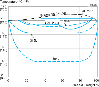
Figure 4. Isocorrosion diagram in formic acid. The curves represent a corrosion rate of 0.1 mm/year (4 mpy) in stagnant test solution.
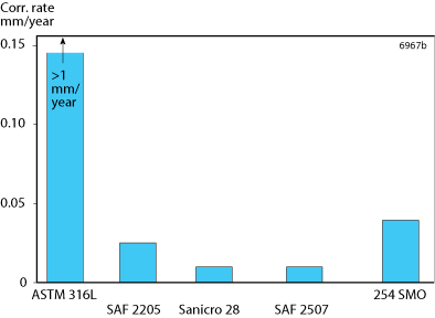
Figure 5. Corrosion rate of various alloys in 80% acetic acid with 2000 ppm chloride ions at 90°C.
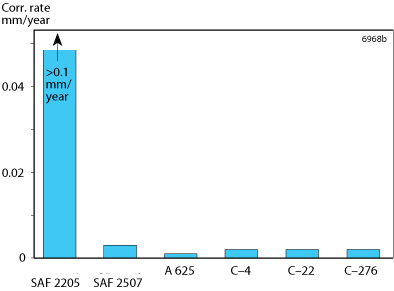
Figure 6. Corrosion rate of various alloys in concentrated acetic acid with 200 ppm chloride ions.
Practical experience with SAF™ 2507 in organic acids, e.g. in terephthalic acid plants, has shown that this alloy is highly resistant to this type of environment. The alloy is therefore a competitive alternative to high alloyed austenitics and nickel alloys in applications where standard austenitic stainless steels corrode at a high rate.
Resistance to inorganic acids is comparable to, or even better than that of high alloy austenitic stainless steels in certain concentration ranges. Figures 7 to 9 show isocorrosion diagrams for sulfuric acid, sulfuric acid contaminated with 2000 ppm chloride ions, and hydrochloric acid, respectively.
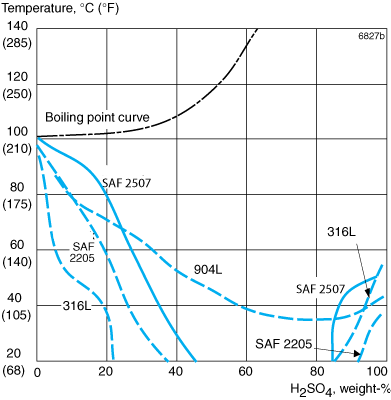
Figure 7. Isocorrosion diagram in naturally aerated sulfuric acid. The curves represent a corrosion rate of 0.1 mm/year (4 mpy) in a stagnant test solution.
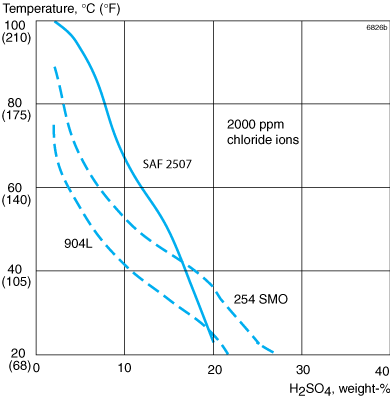
Figure 8. Isocorrosion diagram, 0.1 mm/year (4 mpy) in a naturally aerated sulfuric acid containing 2000 ppm chloride ions.
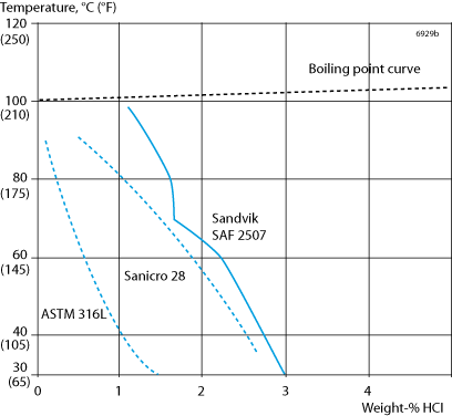
Figure 9. Isocorrosion diagram in hydrochloric acid. The curves represent a corrosion rate of 0.1 mm/year (4 mpy) in stagnant test solution.
Pitting and crevice corrosion
The pitting and crevice corrosion resistance of stainless steel is primarily determined by the content of chromium, molybdenum and nitrogen. The manufacturing and fabrication practices, e.g. welding, are also of vital importance for the actual performance in service.
A parameter for comparing the resistance to pitting in chloride environments is the PRE number (Pitting Resistance Equivalent).
The PRE is defined as, in weight-%
PRE = %Cr + 3.3 x %Mo + 16 x %N
For duplex stainless steels the pitting corrosion resistance is dependent on the PRE value in both the ferrite phase and the austenite phase, so that the phase with the lowest PRE value will be limiting for the actual pitting corrosion resistance. In SAF™ 2507 the PRE value is equal in both phases, which has been achieved by a careful balance of the elements.
The minimum PRE value for SAF™ 2507 seamless tubes is 42.5. This is significantly higher than e.g. the PRE values for other duplex stainless steels of the 25Cr type which are not super-duplex. As an example, UNS S31260 25Cr3Mo0.2N has a minimum PRE-value of 33.
One of the most severe pitting and crevice corrosion tests applied to stainless steel is ASTM G48, i.e. exposure to 6% FeCI3 with and without crevices (method A and B respectively). In a modified version of the ASTM G48 A test, the sample is exposed for periods of 24 hours. When pits are detected together with a substantial weight loss (>5 mg), the test is interrupted. Otherwise, the temperature is increased by 5 °C (9 °F) and the test is continued with the same sample. Figure 11 shows critical pitting and crevice temperatures (CPT and CCT) from the test.
Potentiostatic tests in solutions with different chloride contents are presented in Figure 11. Figure 12 shows the effect of increased acidity. In both cases the applied potential is 600 mV vs SCE, a very high value compared with that normally associated with natural unchlorinated seawater, thus resulting in lower critical temperatures compared with most practical service conditions.
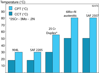
Figure 10. Critical pitting and crevice temperatures in 6% FeCl3, 24h (similar to ASTM G48).
The scatter band for SAF™ 2507 and 6Mo+N illustrates the fact that both alloys have similar resistance to pitting, and CPT-values are within the range shown in the figure.
Tests were performed in natural seawater to determine the critical crevice corrosion temperature of samples with an applied potential of 150 mV vs SCE. The temperature was raised by 4°C (7oF) steps every 24 hours until crevice corrosion occurred. The results are shown in the table below.
| Alloy | CCT (°C) |
|---|---|
| SAF 2507 | 64 |
| 6Mo+N | 61 |
In these tests the propagation rates of initiated crevice corrosion attacks, at 15-50°C (59-122°F) and an applied potential of 150 mV vs SCE were also determined. These were found to be around ten times lower for SAF™ 2507 than for the 6Mo+N alloy.
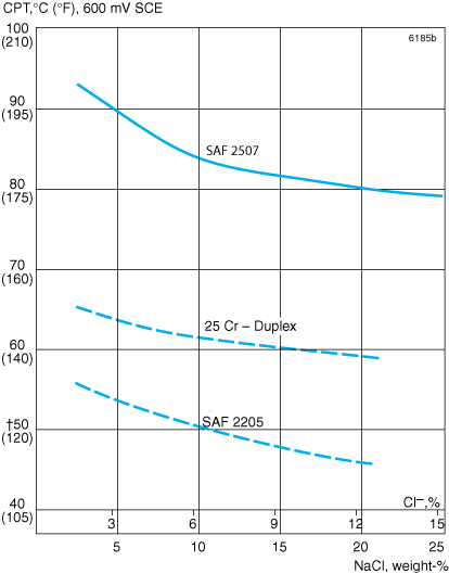
Figure 11. Critical pitting temperatures (CPT) at varying concentrations of sodium chloride, from 3 to 25% (potentiostatic determination at +600 mV SCE with surface ground with 600 grit paper).
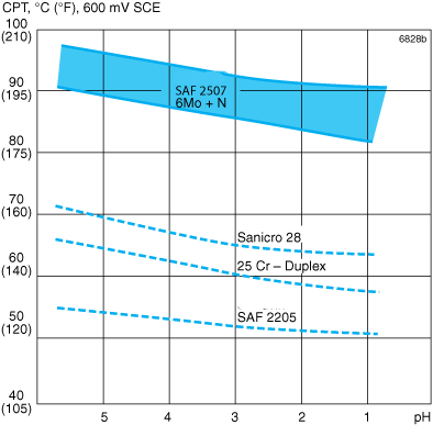
Figure 12. Critical pitting temperatures (CPT) in 3% NaCl with varying pH (potentiostatic determination at +600 mV SCE with surface ground with 600 grit paper).
The corrosion resistance of SAF™ 2507 in oxidizing chloride solutions is illustrated by critical pitting temperatures (CPT) determined in a 'Green death' -solution (1% FeCI3 + 1% CuCl2 +11% H2SO4 + 1.2% HCI) and in a 'Yellow death' -solution (0.1 % Fe2(SO4)3 + 4% NaCl + 0.01 M HCI). The table below shows CPT-values for different alloys in these solutions. It is clear that the values for SAF™ 2507 are on the same level as those for the nickel alloy UNS N06625. The tests demonstrate a good correlation with the ranking of alloys for use as reheater tubes in flue gas desulfurization systems.
Critical pitting temperature (CPT) determined in different test solutions.
| Alloy | Critical pitting temperature (CPT), °C 'Green death' |
'Yellow death' |
|---|---|---|
| SAF™ 2507 | 72.5 | >90 |
| 6Mo+N | 70 | >90 |
| UNS N06625 | 67.5 | >90 |
| ASTM 316 | <25 | 20 |
Stress corrosion cracking
SAF™ 2507 has excellent resistance to chloride induced stress corrosion cracking (SCC).
The SCC resistance of SAF™ 2507 in chloride solutions at high temperatures is illustrated in Figure 13. There were no signs of SCC up to 1000 ppm Cl-/300°C and 10000 ppm Cl-/250°C.
SAF™ 2507 U-bend specimens exposed for 1000 hours in hot brine (108°C, 226°F, 25% NaCl) showed no cracking.
The threshold stress for SAF 2507® in 40% CaCl2 at 100 °C (210 °F) and pH = 6.5 is above 90% of the tensile strength for both parent metal and welded joints (TIG-welded with Alleima® 25.10.4.L or MMA-welded with Alleima® 25.10.4.LR).
Figure 14 shows the result of testing in 40% CaCl2 at 100 °C (210 °F) acidified to pH = 1.5. Acidifying of the standard test solution to pH = 1.5 lowers the threshold stress for SAF™ 2205, but not for SAF™ 2507. This applies to both parent metal and welded joints.
The threshold stress for both parent metal and welded joints of SAF™ 2507 in boiling 45% MgCl2 , 155°C (311°F) (ASTM G36), is approximately 50% of the proof strength.
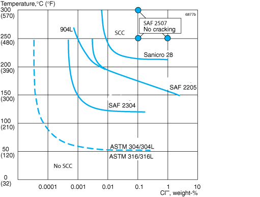
Figure 13. SCC resistance in oxygen-bearing (abt. 8 ppm) neutral chloride solutions. Testing time 1000 hours. Applied stress equal to proof strength at testing temperature.
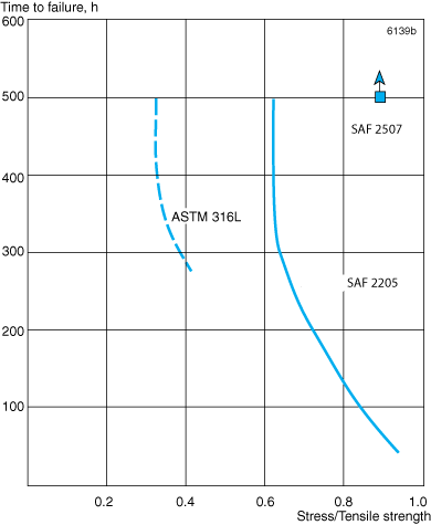
Figure 14. Results of SCC tests with constant load in 40% CaCl2, pH=1.5, at 100 °C (210°F) with aerated test solution.
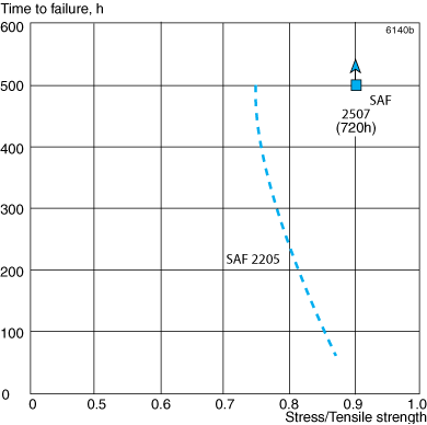
Figure 15. Constant load SCC tests in NACE solution at room temperature (NACE TM 0177).
Figure 15 shows the results of SCC tests at room temperature in NACE TM0177 Test solution A (5% sodium chloride and 0.5% acetic acid saturated with hydrogen sulfide). No cracking occurred on SAF™ 2507, irrespective of the applied stress.
In aqueous solutions containing hydrogen sulfide and chlorides, stress corrosion cracking can also occur on stainless steels at temperatures below 60 °C (140 °F). The corrosivity of such solutions is affected by acidity and chloride content. In direct contrast to the case with ordinary chloride-induced stress corrosion cracking, ferritic stainless steels are more sensitive to this type of stress corrosion cracking than austenitic steels.
In accordance with ISO 15156/NACE MR 0175 solution annealed and rapid cooled wrought SAF™ 2507 is suitable for use at temperatures up to 450 °F (232 °C) in sour environments in oil and gas production, if the partial pressure of hydrogen sulphide does not exceed 3 psi (0.20 bar).
SAF™ 2507, with a maximum hardness of 32 HRC, solution annealed and rapidly cooled, according to NACE MR0103, is suitable for use in sour petroleum refining.
Hydrogen Induced Stress Cracking (HISC)
Hydrogen Induced Stress Cracking (HISC) is an embrittlement phenomenon that may occur in cathodically protected subsea steel constructions in the presence of high tensile stresses. When connected to cathodically protected carbon steels, super duplex stainless steels will also be cathodically protected even though this is not necessary. At the prevalent low electrochemical potentials, atomic hydrogen will be generated on the steel surfaces by the reduction of sea water. Embrittlement due to HISC may occur when hydrogen diffuses into the metal.
Hydrogen diffuses much faster in the ferrite phase than in the austenite phase. Therefore, ferritic steels and ferrite containing steels, e.g. super duplex stainless steels, are more susceptible to HISC than austenitic stainless steels. A high mechanical stress increases the risk of HISC by increasing the hydrogen diffusion rate, crack initiation and propagation in the material.
In super duplex stainless steels, cracks tend to propagate in the embrittled ferrite phase and arrest at ferrite-austenite phase boundaries. Susceptibility to HISC significantly increases with increasing austenite spacing. Coarse-grained microstructures are therefore more susceptible. A testing program performed at Alleima Materials Technology has confirmed that tendency to HISC is reduced when austenite spacing is less than 30 μm, as recommended by DNV RP-F112. Cold pilgered and solution annealed tubes with austenite spacing between 5-15 μm have shown very good resistance to HISC under applied stress up to 130% of the yield strength without cracking.
The acceptable stress without HISC occurring for products with different austenite spacing is illustrated in figure 16.
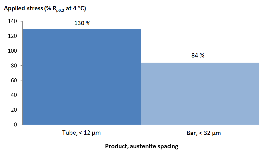
Figure 16. Tolerable stress as a percentage of the actual yield strength at 4°C without HISC occurring is schematically shown for tube and bar products with different austenite spacing. SAF™ 2507 (UNS S32750) has been tested on hydrogen pre-charged tensile specimens, using constant load with a dead weight, with an applied potential of -1050 mV/SCE in a electrochemical cell with 3% NaCl solution at 4°C, 500 hours. [NACE paper no. 07498]
Intergranular corrosion
SAF™ 2507 is a member of the family of modern duplex stainless steels whose chemical composition is balanced to give quick reformation of austenite in the high temperature heat affected zone of a weld. This results in a microstructure that provides the material with good resistance to intergranular corrosion. SAF™ 2507 passes testing to ASTM A262 Practice E (Strauss test) without reservation.
Erosion corrosion
The mechanical properties combined with corrosion resistance give SAF™ 2507 a good resistance to erosion corrosion. Testing in sand containing media has shown that SAF™ 2507 has an erosion corrosion resistance better than corresponding austenitic stainless steels. Figure 17 below shows the relative mass loss rate of the duplex SAF™ 2507, SAF™ 2205 and an austenitic 6Mo+N type steel after exposure to synthetic seawater (ASTM D-1141) containing 0.025-0.25% silica sand at a velocity of 8.9-29.3 m/s (average of all tests is shown).
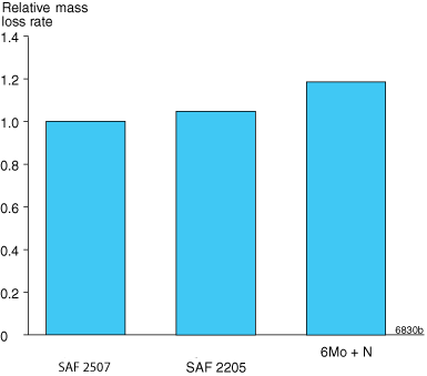
Figure 17. Relative mass loss rate after testing of the resistance against erosion corrosion.
Corrosion fatigue
Duplex stainless steels which have a high tensile strength usually have a high fatigue limit and high resistance to both fatigue and corrosion fatigue.
The high fatigue strength of SAF™ 2507 can be explained by its good mechanical properties, while its high resistance to corrosion fatigue has been proven by fatigue testing in corrosive media.
Applications
SAF™ 2507 is a duplex stainless steel especially designed for service in aggressive chloride-containing environments. Typical applications are:
| Oil and gas exploration and production |
Chloride-containing environments such as seawater handling and process systems. Hydraulic and process fluid tubes in umbilicals |
|---|---|
| Seawater cooling |
Tubing for heat exchangers in refineries, chemical industries, process industries and other industries using seawater or chlorinated seawater as coolant |
| Salt evaporation | Evaporator tubing for production of corrosive salts, e.g. chlorides, sulfates and carbonates |
| Desalination plants |
Pressure vessels for reverse osmosis units, tube and pipe for seawater transport, heat exchanger tubing |
| Geothermal wells |
Heat exchangers in geothermal exploitation units, systems exposed to geothermal or high salinity brines, tubing and casing for production |
| Oil refining and petrochemical and gas processing | Tubes and pipes where the process environment contains a high amount of chlorides, or is contaminated with hydrochloric acid |
| Pulp and paper production |
Material for chloride-containing bleaching environments |
| Chemical processing |
Organic acid plants, also when process solutions are contaminated with e.g. chlorides |
| Mechanical components requiring high strength |
Propeller shafts and other products subjected to high mechanical load in seawater and other chloride-containing environments |
| Desulfurization units | As reheater tubes in flue gas desulfurization systems. The good mechanical and corrosion properties make SAF™ 2507 an economical choice in many applications by reducing the life cycle cost of equipment. |
Fabrication
Bending
The starting force needed for bending is slightly higher for SAF™ 2507 than for standard austenitic stainless steels (ASTM 304L and 316L).
If the service conditions are on the limit of the stress corrosion resistance of SAF™ 2507 heat treatment is recommended after cold bending. For pressure vessel applications in Germany and the Nordic countries, heat treatment may be required after cold deformation in accordance with VdTÜV-Wb 508 and NGS 1609. Heat treatment should be carried out by solution annealing (See under Heat treatment) or resistance annealing.
Hot bending is carried out at 1125-1025°C (2060-1880°F) and should be followed by solution annealing.
Expanding
Compared to austenitic stainless steels, SAF™ 2507 has a higher proof and tensile strength. This must be kept in mind when expanding tubes into tubesheets. Normal expanding methods can be used, but the expansion requires higher initial force and should be undertaken in one operation. As a general rule, tube to tubesheet joints should be welded if the service conditions include a high chloride concentration, thus limiting the risk of crevice corrosion.
Machining
Being a two-phase material (austenitic-ferritic) SAF™ 2507 will present a different tool wear profile from that of single-phase steels of type ASTM 304L. The cutting speed must therefore be lower than that recommended for ASTM 304L. It is recommended that a tougher insert grade is used than when machining austenitic stainless steels, e.g. ASTM 304L.
Forms of supply
Seamless tube and pipe– finishes and dimensions
Seamless tube and pipe in SAF™ 2507 is supplied in dimensions up to 260 mm outside diameter. The delivery condition is solution annealed and either white pickled, or bright annealed.
Other forms of supply:
- Welded tube and pipe
- Fittings and flanges
- Plate, sheet and wide strip
- Bar steel
- Forged products
- Cast products
Heat treatment
The tubes are normally delivered in heat treated condition. If additional heat treatment is needed due to further processing the following is recommended.
Solution annealing
1050-1125°C (1920-2060°F), rapid cooling in air or water.
Mechanical properties
The following figures apply to material in the solution annealed condition. Tube and pipe with wall thickness above 20 mm (0.787 in.) may have slightly lower values. For seamless tubes with a wall thickness <4 mm we guarantee proof strength (Rp0.2) values that are 50 MPa higher than those listed below at 20°C (68°F) as well as those listed at higher temperatures. More detailed information can be supplied on request.
At 20°C (68°F)
Tube and pipe with wall thickness max. 20 mm (0.79 in.).
| Proof strength, MPa | Tensile strength, MPa | Elongation, % | Hardness, HRC | ||
|---|---|---|---|---|---|
| Rp0.2a) | Rp1.0a) | Rm | Ab) | A2" | |
| ≥550 | ≥640 | 800-1000 | ≥25 | ≥15 | ≤32 |
| Proof strength, ksi | Tensile strength, ksi | Elongation, % | Hardness, HRC | ||
|---|---|---|---|---|---|
| Rp0.2a) | Rp1.0a) | Rm | Ab) | A2" | HRC |
| ≥80 | ≥93 | 116-145 | ≥25 | ≥15 | ≤32 |
1 MPa = 1 N/mm2
a) Rp0.2 and Rp1.0 correspond to 0.2% offset and 1.0% offset yield strength, respectively.
b) Based on L0 = 5.65 √S0 where L0 is the original gauge length and S0 the original cross-section area.
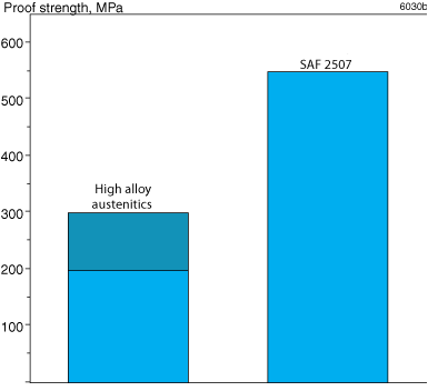
Figure 1. Comparison of minimum proof strength, 0.2% offset, of SAF™ 2507 and high alloy austenitic grades, for material in the solution annealed condition.
At high temperatures
If SAF™ 2507 is exposed to temperatures exceeding 250°C (480°F), for prolonged periods, the microstructure changes, which results in a reduction in impact strength. This does not necessarily affect the behavior of the material at the operating temperature. For example, heat exchanger tubes can be used at higher temperatures without any problems. Please contact Alleima for more information. For pressure vessel applications, 250°C (480°F) is required as a maximum, according to VdTÜV-Wb 508 and NGS 1609.
Tube and pipe with wall thickness max. 20 mm (0.79 in.)
| Temperature, °C | Proof strength Rp0.2, MPa |
|---|---|
| min. | |
| 50 | 530 |
| 100 | 480 |
| 150 | 445 |
| 200 | 420 |
| 250 | 405 |
| 300 | 395 |
| Temperature, °F | Proof strength Rp0.2, ksi |
|---|---|
| min. | |
| 120 | 77.0 |
| 200 | 70.5 |
| 300 | 64.5 |
| 400 | 61.0 |
| 500 | 58.5 |
| 600 | 57.0 |
Seamless tube and pipe in the cold-worked condition
| Proof strength | Tensile strength | Elong. | Hardness, HRC | ||
|---|---|---|---|---|---|
| Rp0.2 | Rm | A2" | |||
| MPa | ksi | MPa | ksi | % | |
| 862 - 1034 | 125-150 | ≥ 896 | ≥ 130 | ≥ 10 | ≤ 37 |
| 965 - 1103 | 140-160 | ≥1000 | ≥ 145 | ≥ 9 | ≤ 38 |
Impact strength
SAF™ 2507 possesses good impact strength. The ductile brittle transition temperature is below -50°C (-58°F). The impact strength of welded SAF™ 2507 is also good, although the values are lower than the base metal. The impact strength, if gas shielded arc weldments, is a minimum of 27 J (20 ft lb) at a temperature of -50°C (-58°F).
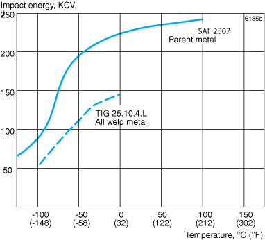
Figure 2. Typical impact energy curves for SAF™ 2507 using standard Charpy V specimens (average of 3 at each temp.). Parent metal samples taken in the longitudinal direction from 260 x 12 mm hot extruded and solution annealed (1075°C / 1965°F) tube. All weld metal samples from Alleima® 25.10.4.L TIG wire.
According to ASME B31.3 the following design values are recommended for UNS S32750 (SAF™ 2507):
| Temperature | Stress | ||
|---|---|---|---|
| °F | °C | ksi | MPa |
| 100 | 38 | 38.7 | 267 |
| 200 | 93 | 38.5 | 265 |
| 300 | 149 | 36.4 | 251 |
| 400 | 204 | 35.4 | 244 |
| 500 | 260 | 34.5 | 238 |
| 600 | 316 | 34.3 | 236 |
Physical properties
Density: 7.8 g/cm3, 0.28 lb/in.3
Specific heat capacity
Metric units Imperial units
| Temperature, °C | J/(kg °C) | Temperature, °F | Btu/(lb °F) |
|---|---|---|---|
| 20 | 490 | 68 | 0.12 |
| 100 | 505 | 200 | 0.12 |
| 200 | 520 | 400 | 0.12 |
| 300 | 550 | 600 | 0.13 |
| 400 | 585 | 800 | 0.14 |
Thermal conductivity
Metric units, W/(m °C)
| Temperature, °C | 20 | 100 | 200 | 300 | 400 |
|---|---|---|---|---|---|
| SAF 2507 | 14 | 15 | 17 | 18 | 20 |
| ASTM 316L | 14 | 15 | 17 | 18 | 20 |
Imperial units, Btu/(ft h °F)
| Temperature, °F | 68 | 200 | 400 | 600 | 800 |
|---|---|---|---|---|---|
| SAF™ 2507 | 8 | 9 | 10 | 11 | 12 |
| ASTM 316L | 8 | 9 | 10 | 10 | 12 |
Thermal expansion
SAF™ 2507 has a coefficient of thermal expansion close to that of carbon steel. This gives SAF™ 2507 definite design advantages over austenitic stainless steels in equipment comprising of both carbon steel and stainless steel. The values given below are average values in the temperature ranges.
| Temperature, °C | 30-100 | 30-200 | 30-300 | 30-400 |
|---|---|---|---|---|
| SAF™ 2507 | 13.5 | 14.0 | 14.0 | 14.5 |
| Carbon steel | 12.5 | 13.0 | 13.5 | 14.0 |
| ASTM 316L | 16.5 | 17.0 | 17.5 | 18 |
| Temperature, °F | 86-200 | 86-400 | 86-600 | 86-800 |
|---|---|---|---|---|
| SAF™ 2507 | 7.5 | 7.5 | 8.0 | 8.0 |
| Carbon steel | 6.8 | 7.0 | 7.5 | 7.8 |
| ASTM 316L | 9.0 | 9.5 | 10.0 | 10.0 |
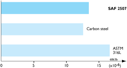
Figure 3. Thermal expansion, per °C (30-100°C, 86-210°F).
Resistivity
| Temperature, °C | μΩm | Temperature, °F | μΩin. |
|---|---|---|---|
| 20 | 0.83 | 68 | 32.7 |
| 100 | 0.89 | 200 | 34.9 |
| 200 | 0.96 | 400 | 37.9 |
| 300 | 1.03 | 600 | 40.7 |
| 400 | 1.08 | 800 | 43.2 |
Modulus of elasticity, (x103)
| Temperature, °C | MPa | Temperature, °F | ksi |
|---|---|---|---|
| 20 | 200 | 68 | 29.0 |
| 100 | 194 | 200 | 28.2 |
| 200 | 186 | 400 | 27.0 |
| 300 | 180 | 600 | 26.2 |
Welding
Welding
The weldability of SAF™ 2507 is good. Welding must be carried out without preheating and subsequent heat treatment is normally not necessary. Suitable methods of fusion welding are manual metal-arc welding (MMA/SMAW) and gas-shielded arc welding, with the TIG/GTAW method as first choice.
For SAF™ 2507, heat input of 0.2-1.5 kJ/mm and interpass temperature of <150°C (300°F) are recommended.
Recommended filler metals
GTAW/TIG welding
ISO 14343 S 25 9 4 N L / AWS A5.9 ER2594 (e.g. Exaton 25.10.4.L)
MMA/SMAW welding
ISO 3581 E 25 9 4 N L R / AWS A5.4 E2594-16 (e.g. Exaton 25.10.4.LR)
ISO 3581 E 25 9 4 N L B / AWS A5.4 E2594-15 (e.g. Exaton 25.10.4.LB)
Overlay welding
ISO 14343 S 25 9 4 N L / AWS A5.9 ER2594 (e.g. Exaton 25.10.4.L) wire or strip electrodes are recommended for overlay welding of tube sheets and high-pressure vessels in cases where corrosion resistance, equal to that of SAF 2507®, is required.
Disclaimer: Recommendations are for guidance only, and the suitability of a material for a specific application can be confirmed only when we know the actual service conditions. Continuous development may necessitate changes in technical data without notice. This datasheet is only valid for Alleima materials.