High-performance tube materials for syngas coolers
For convection syngas coolers, CSC, where the corrosive syngas is inside the tube and the water/steam is on the outside, Alleima has developed a composite tube consisting of HT5/Sanicro® 30 (ASTM/ASME T12/UNS N08800).
In the case of a radiant syngas cooler design, with syngas on the outside of the tube and water/steam on the inside, Alleima supplies single-component austenitic stainless steel tubes in grades Sanicro® 30 (UNS N08800, EN 1.4558) and Sanicro® 28 (UNS N08028, EN 1.4563).
Gasification
Gasification is a method of producing synthesis gas, syngas, from different types of organic material, e.g. coal, petroleum products, biomass, or waste. Syngas can be further processed into various chemicals and/ or used for the production of electricity. Energy conversion of syngas into electricity as well as carbon capture is potentially more efficient and easier to achieve than through direct combustion. After gasification, gas is cooled and heat is recovered in syngas coolers. Syngas can be corrosive which means higher alloyed materials and special products have to be used.
Excellent corrosion resistance
The high-alloy stainless component (Sanicro® 30) provides excellent protection against corrosive syngas. The gas is a mixture of CO, H2, H2O, CO2, N2, HCl, and H2S, which result in a reducing atmosphere. The low-alloy ferritic steel (Alleima HT5), carrying the steam side
pressure reduces the risk of steam side induced stress corrosion cracking (SCC).
Attractive design properties
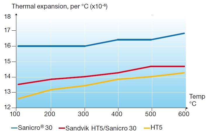
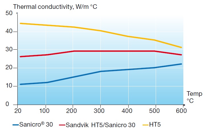
The metallurgical bond between the inner and outer tube components ensures the mechanical integrity of the tube even after bending. The bond also guarantees the effectiveness of the respective properties of the two materials. Since the corrosion-resistant alloy is normally thinner than the load carrier, the values of thermal expansion and thermal conductivity of a composite tube are closer to the values of the low-alloy component. Compared with a single-component stainless tube, this means lower stresses, due to lower thermal elongation and lower tube metal temperature.
Practical experience
About 10,000 meters (32808.4 ft) of Alleima HT5/Sanicro® 30 composite tubes were manufactured and supplied for two US coal gasification projects in 1994/95. The two IGCC projects started up in 1995 and 1996. In 2009 additional 2,000 meters (6600 ft) were produced for a replacement syngas cooler tube for one of these projects. The new vessel was installed in 2010. The tubes used in the old cooler were investigated and showed only limited material degeneration. The thickness of the stainless steel component was still within the tolerances of the as-delivered tubes after 15 years of operation. Another 5000 meters (16400 ft) were produced in 2010 and 18,000 meters (59100 ft) in 2011/2012 for gasification projects in North America and Asia.
Grades
Outer component
Alleima HT5 (ASTM/ASME SA-213/T12, EN 1.7335).
| C | Si | Mn | P | S | Cr | Mo |
| 0.10 | 0.25 | 0.5 | ≤0.025 | ≤0.025 | 1.0 | 0.5 |
Density: Alleima HT5 = 7.9 g/m3
Inner component
Sanicro® 30 (ASME SB407, UNS N08800, EN 1.4558).
| C | Si | Mn | P | S | Cr | Ni | Ti | Al |
| ≤0.030 | 0.5 | 0.6 | ≤0.020 | ≤0.015 | 20 | 32 | 0.5 | 0.3 |
Density: Sanicro 30 = 8.0 g/cm3
Physical properties
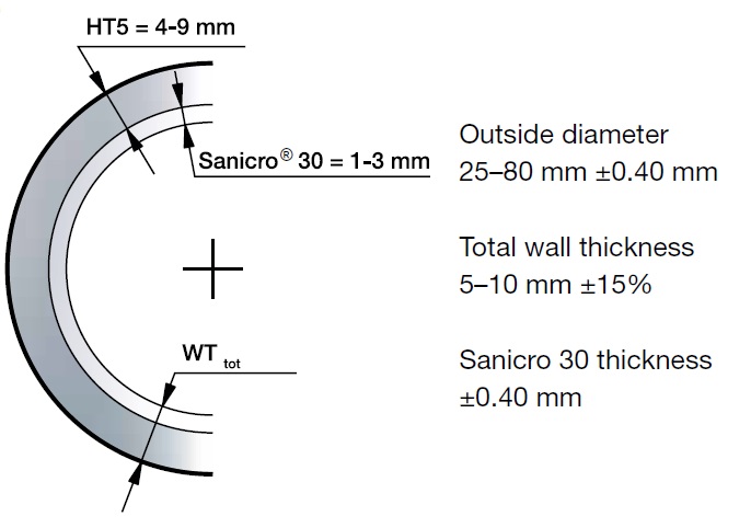
Typically, the thickness of the component made of Sanicro® 30 is between 25 and 30% of the total wall thickness of the composite tube. The calculations of the physical properties of the composite tube are based on a ratio of 25% Sanicro® 30 and 75% Alleima HT5. The data for the outer and inner components are based on real measurements.
Specifications
Alleima tube specification 7-1-1253 ASME SA-213, ASME SA-450, EN 10216-2:2002 + AZ:2007, EN 10216-5.
Sizes and typical tolerances
Wall thickness and wall thickness tolerances. Total minimum wall = Alleima HT5 + Sanicro® 30 (pressure bearing component required in min wall according to ASME Code Sec I and II.).
Welding
Butt welding
Butt welding of composite tubes must be carried out so that dilution is kept under control. Welding a composite tube with the stainless steel as the inner component requires a specific welding procedure, due to the risk of formation of unwanted microstructures e.g., martensite.
To obtain the optimum corrosion resistance and mechanical properties of the welded joints, the following groove preparation (fig. 3) and welding procedures (fig. 4) are recommended, see table 1.
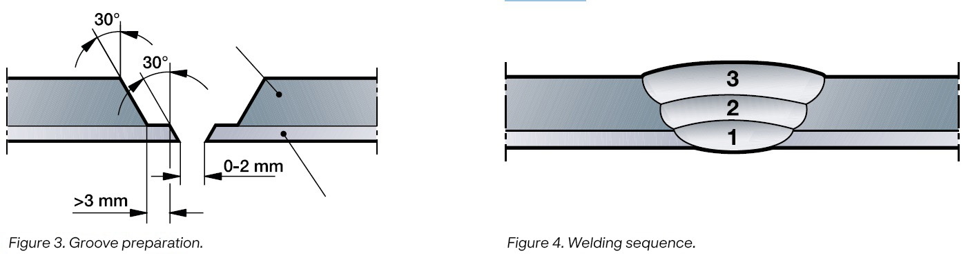
Table 1. Recommended filler metals and welding methods, ref. figure 4
| Option | Inner component (1) | Transition (2) | Outer component (3) | |||
| Method | Filler | Method | Filler | Method | Filler | |
| A | MMA | 1) | MMA | 1) | MMA | 1) |
| TIG | 2) | TIG | 2) | TIG | 2) | |
| B | TIG | 2) | MMA | Fe with low C e.g. OK 53.18 3) | MMA | 4) |
| TIG | Fe with low C | TIG | 5) |
- EN ISO 14172:E Ni6182(NiCr15Fe6Mn/AWS A5.11 ERNiCrFe-3
- EN ISO 18274: S Ni6082(NiCr20Mn3Nb)/AWS A5.14 ERNiCr-3
- EN ISO 2560-A:E 38 2B 3 2 H10/AWS A5.1:E7016
- EN ISO 3580-A:E CrMo1B4 2 H5/AWS A5.5:E8018-B2
- EN ISO 21952-A:G CrMo1Si/EN ISO 21952-B:G55M1CM2/AWS A5.28: ER 80S-G