Product and product history
Composite tubes consist of an external layer of stainless steel, metallurgically bonded to an internal load-carrying layer of normal boiler tube material. All composite tubes are subject to a 100% ultrasonic examination to check for inner and outer surface defects and to verify the metallurgical bond.
Alleima has been producing composite tubes since the early 1970s. The biggest application is furnace walls in recovery boilers for the pulp and paper industry. More than 1.5 million meters in 3R12/4L7 have been supplied to more than 250 recovery boilers worldwide.
Grades
Outer component Sanicro® 38, type UNS N08825, Mod. Alloy 825, W.-Nr. 2.4858.
Chemical composition (nominal), %
| C | Si | Mn | Cr | Ni | Mo | Cu | Ti |
| ≤0.030 | ≤0.5 | 0.8 | 20 | 38.5 | 2.6 | 1.7 | 0.8 |
Inner component Alleima 4L7, type ASME SA-210 A1, EN P265GH, EN 1.0425, W.-Nr. 1.0405, St 45.8.III, SS 1435.
Chemical composition (nominal), %
| C | Si | Mn | P | S |
| ≤0.18 | ≤0.3 | 0.7 | ≤0.030 | ≤0.030 |
Specifications
Alleima spec. 7-1-0009
ASME Code Section 1 and Section II
VD-TÜV Werkstoffblatt 541.03.2001
TÜV Wien Werkstoffblatt 140
Sanicro® 38/4L7 for more severe conditions
Alleima has developed a more resistant composite tube product, Sanicro® 38/4L7*, mainly intended for the floors of recovery boilers. This product has considerably improved corrosion resistance. It is more resistant to SCC, has better fatigue strength, and improved structural stability.
Dimensions and tolerances
Stock standard sizes
| Outside diameter | Total min. wall thickness | Thickness of stainless component | Min. thickness of carbon steel component |
| mm (in.) | mm (in.) | mm (in.) | mm (in.) |
| 50.8 (2) | 5.08 (.200) | 1.42 (.056) | 3.66 (.144) |
| 63.5 (2.5) | 6.53 (.257) | 1.82 (.072) | 4.71 (.185) |
| 76.2 (3) | 6.58 (.259) | 1.86 (.073) | 4.72 (.186) |
Other dimensions can be supplied on request.
Tolerances
Permissible variations in O.D. and wall thickness
Outside diameter: ± 0.5%
Total wall thickness: +15/-0%
Thickness of stainless steel component: ± 0.40 mm (0.016 in.)
The thickness of the stainless steel component is checked by testing the entire length of each tube.
Welding
Butt welding
Butt welding of composite tubes must be carried out in such a manner that dilution of the components is kept under control. The melting point of the bonding zone is lower than the melting point of the stainless steel, and, if the bonding zone is exposed to too much heat, a local melting may occur. Therefore, in order to obtain the optimum corrosion resistance and mechanical properties of the welded joints, the following edge preparation (fig. 2) and welding sequences (fig. 3) are recommended. See table 1.
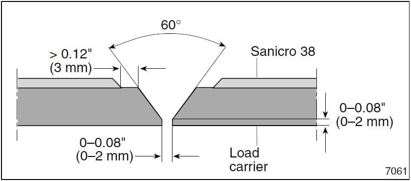 Fig. 2 Edge preparation
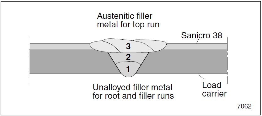 Fig 3. Welding sequence
Table 1. Filler metals and welding methods for butt welding.
| Pass | Welding method | Filler metal options specification | Max. heat input 1) | Max. interpass temp. |
| kJ/mm (kJ/in) | ºC (ºF) | |||
| Carbon Steel | TIG/MIG | Matching filler AWS A5.18: ER 70 S-6 | 2.5 (63) | - |
| (No. 1 – 2) | MMA | Matching filler AWS A5.1E 7018 | 2.5 (63) | - |
| Stainless Steel | TIG/MIG | Alleima 27.31.4.LCu AWS A5.9 ER 383 | 1 (25) | 150 (300) |
| (No. 3) | TIG/MIG | Sanicro 60 AWS A5.14 ER NiCrMo-3 2) | 1 (25) | 100 (212) |
| MMA 3) | Alleima 27.31.4.LCuR AWS A5.4 E 383-16 | 1 (25) | 150 (300) | |
| MMA 3) | Sanicro 60 AWS SFA5.11 E NiCrMo-3 2) | 1 (25) | 100 (212) |
1) A higher heat input may be applied for the root- and filler runs, if the stainless peel off is increased.
2) Sanicro® 60 for waste incineration boilers.
3) MMA is recommended for manual welding to ensure low penetration and maintenance of the carbon steel cross-section of the butt weld.
Panel welding
Two types of panels are normally fabricated: either tangential panels, tubes joined directly by a weld, or finned panels, with tubes linked by fins (see figs. 4 and 5).
In both cases, shop welding must be carried out with a machine specially designed for the purpose. The weld should not penetrate the stainless steel layer of the composite tube, as this may result in hot cracking or the formation of brittle weld structures. Furthermore, excessive dilution of the fully austenitic stainless steel filler metal, during fin welding (carbon steel fin), may also lead to hot cracking or a brittle weld structure.
MIG (GMAW/131) or SAW (12) are suitable methods for the fabrication of finned panels. The choice of filler metal depends upon the fin material used. A basic flux should be used in SAW (12). In general, dilution should be minimized, in order to avoid hot cracking or brittle weld metal structures. The impurity level in carbon steel fin materials should be considered, in order to minimize susceptibility to hot cracking.
Thick fins should be beveled, in order to minimize the amount of fin material in the weld (see fig. 4).
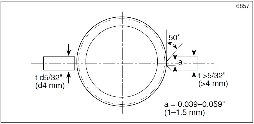 Fig 4. Edge preparation of fins
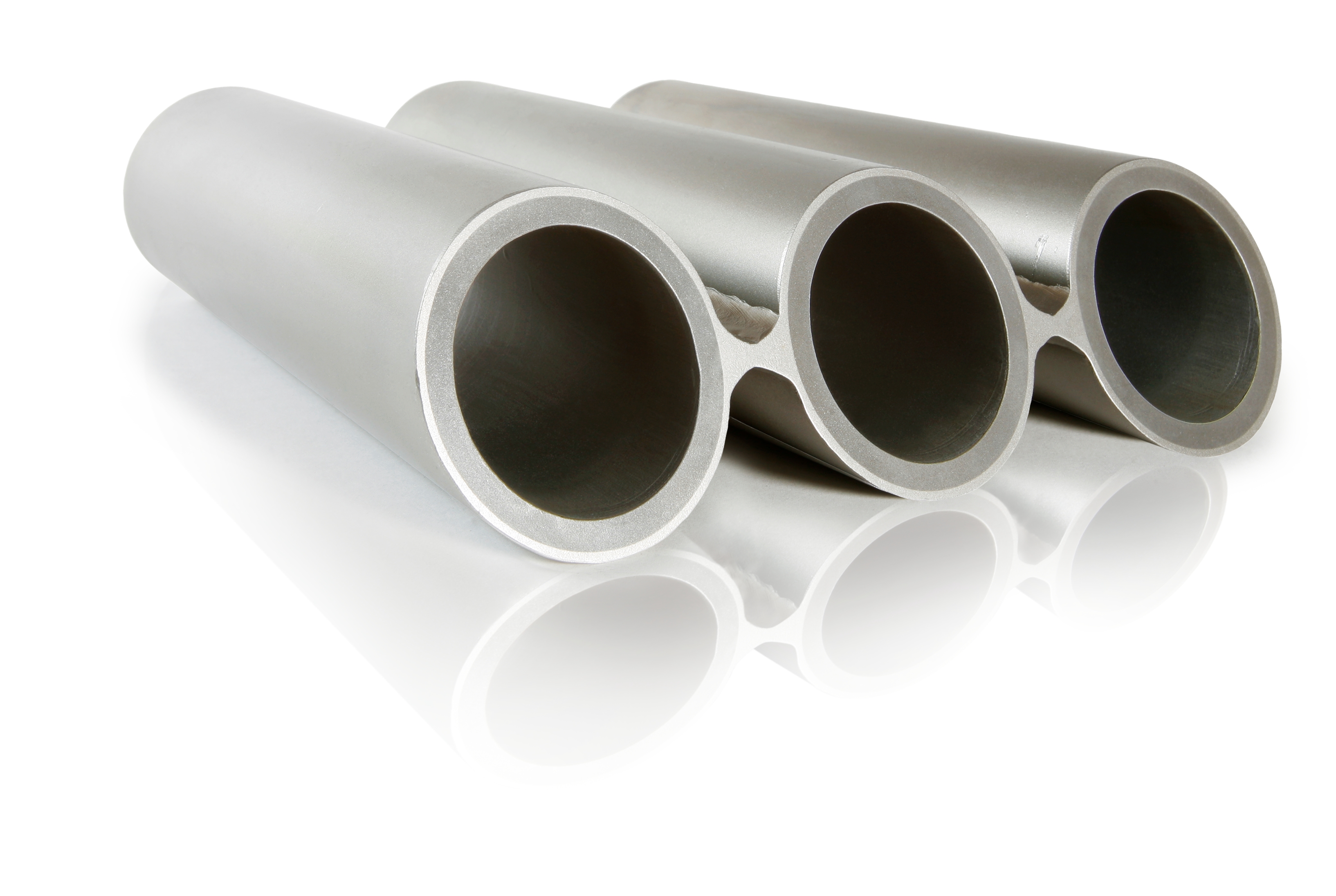 Fig.5 Welded finned panel
Physical properties
| Density | g/cm3 | ib/in3 |
| 4L7 | 7.9 | 0.28 |
| Sanicro 38 | 8.1 | 0.30 |
Thermal expansion/conductivity
The composite tube values below have been calculated on a typical size, dimension 63.5 x 6.53 mm min. (2.5 x 0.257" min).
| 3R12 | 1.65 (.065") ave. | Sanicro 38 | 1.82 (.072") ave. |
| 4L7 | 4.88 (.192") min. | 4L7 | 4.71 (.185") min. |
| Total | 6.53 (.257") min | Total | 6.53 (.257") min |
Thermal expansion, mean values in temperature ranges (x10-6)
Per °C
| Temp. ºC | 4L7 | 3R12 | Sanicro 38 | 3R12/4L7 | Sanicro 38/4L7 |
| 30 –100 | 12.3 | 16.5 | 14.2 | 13.4 | 12.8 |
| 30 –200 | 12.8 | 17.2 | 14.6 | 13.9 | 13.3 |
| 30 –300 | 13.5 | 17.7 | 14.9 | 14.6 | 13.9 |
| 30 –400 | 14.0 | 18.0 | 15.1 | 15.0 | 14.3 |
| 30 –500 | 14.3 | 18.4 | 15.3 | 15.3 | 14.6 |
Per °F
| Temp. ºF | 4L7 | 3R12 | Sanicro 38 | 3R12/4L7 | Sanicro 38/4L7 |
| 86 – 200 | 6.8 | 9.1 | 7.9 | 7.4 | 7.1 |
| 86 – 400 | 7.1 | 9.6 | 8.1 | 7.7 | 7.4 |
| 86 – 600 | 7.5 | 9.8 | 8.3 | 8.1 | 7.8 |
| 86 – 800 | 7.8 | 10.1 | 8.4 | 8.4 | 8.0 |
| 86 – 1000 | 8.0 | 10.2 | 8.5 | 7.6 | 8.2 |