To meet future demands for an even more resistant product than Sanicro® 38, FP Innovations-Paprican, Canada, and Alleima jointly developed Sanicro® 67.
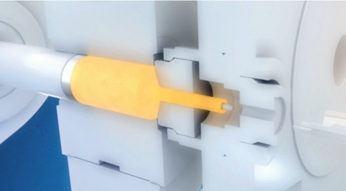 Figure 1. Hot extrusion.The key attributes of Sanicro® 67 are excellent resistance against stress corrosion cracking and very good general corrosion resistance. These properties are gained by a higher chromium content and a low work-hardening rate. This results in a premium composite tube product for severe service, such as air port openings.
The corrosion properties and resistance to stress corrosion cracking have been verified in both extensive laboratory testing and in boilers. Most boiler installations have been in airports. The first installation was in 2009. Evaluation of taken out samples after 6 years of operation showed tubes to be in very good condition.
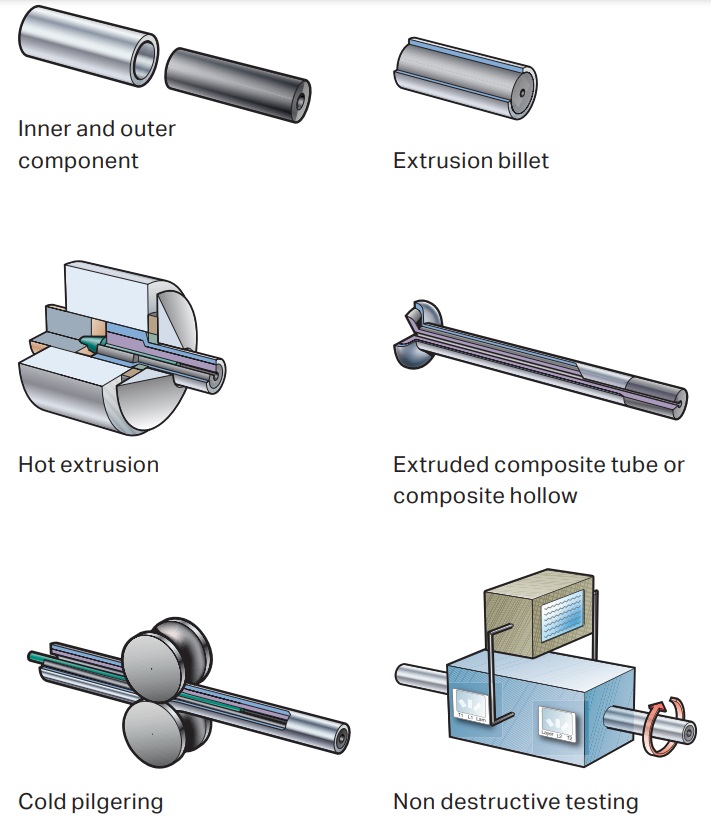 Figure 2. Alleima composite tubes consist of two different materials metallurgically bonded together through hot extrusion. By selecting the correct alloy for the outside and inside component, the corrosion resistance and the mechanical properties are optimised and a tube that meets conflicting material requirements inside and outside is obtained.
Grades
- Outer component: Sanicro® 67, EN 2.4642, UNS N06690.
- Inner component: Alleima® 4L7, EN 1.0425, P265GH, ASME SA-210 A1, or ASME SA210 C
- Inner component: Alleima® 3Mo1, EN 1.5415, 16Mo3 (ASME SA 209 T1, lower Mo content).
Chemical composition, Sanicro® 67 (nominal), %
| C | Si | Mn | P | S | Cr | Ni | Fe |
| 0.02 | ≤0.5 | ≤0.5 | ≤0.020 | ≤0.015 | 30 | Bal (60) | 10 |
Chemical composition, load-carrying (normally inner) components (nominal), %
| Alleima | C | Si | Mn | P | S | Cr | Ni | Mo |
| 4L7 | 0.20 | 0.3 | 0.7 | ≤0.025 | ≤0.020 | ≤0.30 | - | ≤0.08 |
| 3Mo1 | 0.012-0.20 | 0.35 | 0.40-0.90 | ≤0.025 | ≤0.020 | 2.3 | 0.3 | 0.25-0.35 |
Dimensions, standard sizes
| Outside diameter | Total minimum wall thickness | Average thickness of stainless steel component | Average thickness of carbon steel component | ||||
| mm | in. | mm | in. | mm | in. | mm | in. |
| 38 | 1.5 | 5.0 | 0.197 | 1.40 | 0.055 | 3.60 | 0.142 |
| 63.5 | 2.5 | 6.53 | 0.257 | 1.82 | 0.072 | 4.71 | 0.185 |
| 76.2 | 3 | 6.58 | 0.259 | 1.86 | 0.073 | 4.72 | 0.186 |
Specifications
Alleima specification 7-1-0009, PED 97/23/EC, EN 10216-2, EN 12952-2 Annex C, (VD-TÜV Werkstoffblatt 541 03.2001).
Thermal expansion, conductivity
The composite tube values below have been calculated on a typical size dimension 63.5 x 6.53 mm min. (2.5 in. x .257 in.)
| Sanicro® 38 and 67 | = 1.82 mm (0.072 in.) ave. |
| Alleima® 4L7 | = 4.71 mm (0.185 in.) min. |
| = 6.53 mm (0.257 in.) min. |
Tolerances
Permissible variations in outside diameter and wall thickness.
| Outside diameter | 38 mm (1 1/2 in.) ± 0.2 mm (0.008 in.) |
| 50.8 mm (2 in.) ± 0.25 mm (0.010 in.) | |
| 63.5 mm (2 1/2 in.) ± 0.3 mm (0.012 in.) | |
| 76.2 mm (3 in.) ± 0.38 mm (0.015 in.) | |
| Total wall thickness O.D. | <50.8 mm (2 in.); +22%-0 |
| ≥50.8 mm (2 in.); +15%-0 |
Thickness of the stainless steel component
+ 0.60 mm (0.024 in.) – 0.40 mm (0.016 in.) The thickness of the stainless steel component is verified by Eddy current testing of the entire length of each tube.
Thermal expansion, mean values in temperature ranges (10-6) per °C
| Temp. °C | Alleima® 4L7 | Sanicro® 67 | Sanicro® 38 | Sanicro® 38/4L7 | Sanicro® 67/4L7 |
| 30-100 | 12.3 | 13.6 | 14.9 | 13.0 | 12.7 |
| 30-200 | 12.8 | 14.1 | 15.3 | 13.5 | 13.2 |
| 30-300 | 13.5 | 14.5 | 15.7 | 14.1 | 13.8 |
| 30-400 | 14.0 | 14.9 | 16.1 | 14.6 | 14.3 |
| 30-500 | 15.3 | 15.3 | 16.2 | 14.8 | 14.6 |
Thermal conductivity, W/m (BTU/ft h °F)
| °C (°F) | Alleima® 4L7 | Sanicro® 67 | Sanicro® 38 | Sanicro® 38/4L7 | Sanicro® 67/4L7 |
| 23 (73) | 46 (26.5) | 11 (6.5) | 11 (6.5) | 25 (14.5) | 25 (15) |
| 100 (200) | 48 (27.5) | 13 (7.5) | 12 (7) | 27 (15.5) | 29 (17) |
| 200 (400) | 47 | 14 (8.5) | - (-) | - (-) | 29 (17) |
| 300 (600) | 46 (26.5) | 16 (9.5) | 16 (9.5) | 31 (18) | 31 (18) |
| 400 (800) | 44 | 18 (10.5) | - (-) | - (-) | 32 (19) |
| 500 (1000) | 42 (24.5) | 19 (11.5) | 19 (11) | 32 (18.5) | 32 (19) |
Improved corrosion resistance
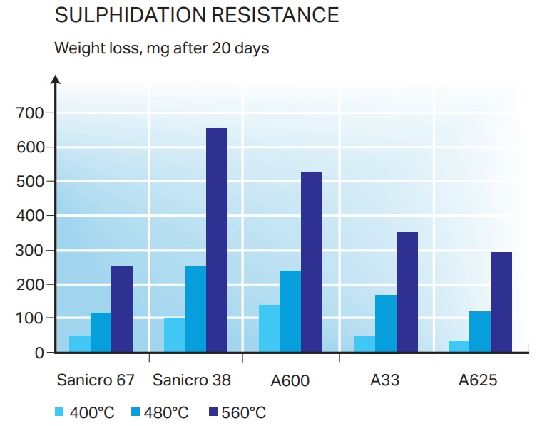 Figure 3. Sanicro® 67 has good resistance to sulphidation in standard test. By courtesy of FPInnovations/Paprican
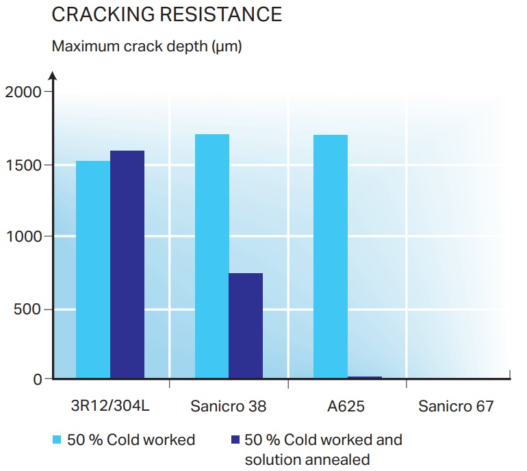 Figure 4. Sanicro® 67 has excellent resistance to cracking in annealed and cold worked state. By courtesy of FPInnovations/Paprican
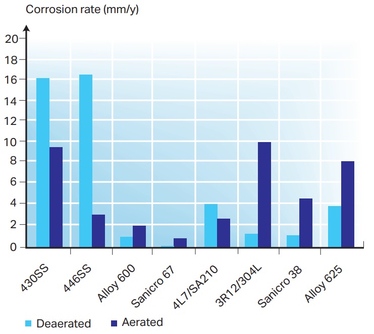 Figure 5. Corrosion tests in simulated air port opening environment. By courtesy of FPInnovations/Paprican.
Welding
Butt welding
Butt welding of composite tubes should be carried out in such a way that dilution is kept under control. The melting point of the bonding zone is lower than the melting point of the stainless steel. If the bonding zone is exposed to excessive heat input, local melting may occur.
The preferred welding method is MMA (SMAW/111) with covered electrodes. TIG (GTAW/141) is also an acceptable method.
In order to obtain the optimum corrosion resistance and mechanical properties of the welding joints, the following edge preparation, figure 6, and welding
sequence, figure 7, are recommended. Recommendations of welding methods, filler metal, and welding parameters are listed in table 1.
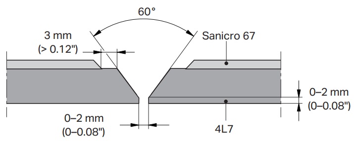 Figure 6. Edge preparation.
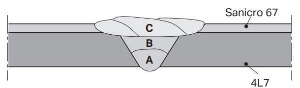 Figure 7. Welding sequence.
Panel welding
The regular way to fabricate panels with Sanicro® 67 composite tubes would be to produce membrane panels, with tubes linked by membranes, see figure 8.
Shop welding of panels should be carried out with a machine specially designed for the purpose. The welding should be performed so that penetration is kept under control and in accordance with customer requirements. Excessive penetration may result in hot cracking or the formation of brittle weld structures. Furthermore, if carbon steel membranes are used excessive dilution of the filler metal could lead to hot cracking or a brittle weld structure.
Submerged arc welding is suitable for fabricating membrane panels, see table 2. The choice of filler metals depends on the membrane material to be used. A basic
flux should be used in SAW welding. The impurity level in carbon steel membrane materials should be considered due to susceptibility to hot cracking.
Table 1. Filler metals and welding methods for butt welding
| Pass (refer to figure 7) | Welding method | Filler metal and specification | Max. heat input, kJ/mm (kJ/in.) | Preheat and interpass temp. °C (°F) | |
| Root & filler run - A & B Carbon steel |
MMA | Matching filler | AWS A5.1 E7018 | 2,5 (63)1 | 250 (480) |
| TIG | Matching filler | AWS A5.18 ER70S-6 | 2,5 (63)1 | 250 (480) | |
| Top run - C Stainless |
MMA | Sanicro 69 | AWS A5.11 ENiCrFe-7 | 1,0 (25) | 150 (300) |
| TIG | Sanicro 68HP | AWS A5.14 ERNiCrFe-7 | 1,0 (25) | 150 (300) | |
1) A higher heat input may be applied for the root and filler runs if the stainless peel off is increased
Table 2. Welding method and consumables for panel welding with membrane material similar to Alloy 690 (Sanicro® 67) and Alloy 825 (Sanicro® 38)
| Welding methods | Welding consumables | Max. heat input, kJ/mm (kJ/in.) |
| SAW | Sanicro® 68HP AWS A5.14 ERNiCrFe-7 & flux Alleima® 50SW |
1,0 (25) |
Thick membranes should be beveled in order to minimize the amount of membrane material in the weld, see figure 8.
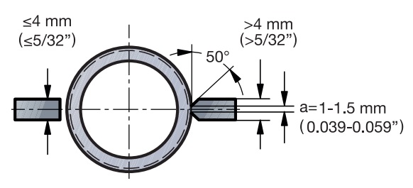 Figure 8. Edge preparation of fins.
Bending
- Composite tubes can be bent by the same methods as those used for single component tubes.
- Cold bending is recommended for radii down to 1.3 x D (≈38 % deformation). For tighter radii, hot bending is recommended.
- Temperatures, holding and quenching times are the same as recommended for carbon steel tubing.
- The low work-hardening rate of Sanicro® 67 significantly reduces the risk of cracking compared to other corrosion resistance alloys such as alloy 625.
For higher steam pressures
Recovery boiler steam pressure has increased during later years which means that the saturated steam temperatures and thereby the surface metal temperatures are increasing (100bar=311C and 150bar=343C). This means that thicker load inner component walls are
required to cope with the design standards.
To reduce the need for increased tube wall thickness Alleima offers two stronger inner component options as follows.
For boilers designed under ASME Boiler and Pressure Vessel Code:
1. ASME SA210 Grade C which has 7% - 17% higher max allowable stress values than the standard SA210 A1 component.
Table showing max allowable stress values for ASME SA210 Grade A1 and Grade C (internal denomination for both 4L7)
| Grade | TC | 300 | 325 | 350 | 375 | 400 | 425 | 450 |
| SA210A1 | MPa | 118 | 118 | 117 | 105 | 88.9 | 75.3 | 62.7 |
| SA210 C | MPa | 138 | 138 | 135 | 123 | 101 | 83.8 | 67 |
| Relation | 1.17 | 1.17 | 1.15 | 1.17 | 1.14 | 1.11 | 1.07 |
For Boilers designed under European PED rules:
2. EN10216-2 EN1.5415, 16Mo3 with 13% to 95% higher strength values than the standard P265GH component.
Table showing creep rupture and minimum proof RP02 at elevated temperature and creep strength according to EN 10216-2 for P265GH (internal denomination 4L7) and 16Mo3 (internal denomination 3Mo1)
| Grade | TC | 350°C | 360°C | 370°C | 380°C | 390°C |
| P265GH | MPa | 141 | 141 | 141 | 141 | 134 |
| 16Mo3 | MPa | 159 | 159 | 169 | 159 | 156 |
| Relation | 1.13 | 1.13 | 1.13 | 1.13 | 1.16 |
| Grade | TC | 400°C | 410°C | 430°C | 440°C | 450°C |
| P265GH | MPa | 128 | 114 | 100 | 88 | 77 |
| 16Mo3 | MPa | 156 | 156 | 156 | 156 | 150 |
| Relation | 1.22 | 1.37 | 1.56 | 1.77 | 1.95 |
These two optional higher strength materials, SA210 Grade C and EN10216-2 16Mo3 allow for design with thinner tube walls compared to normal SA210A1 and P265GH components.