Chromflex™ is a family of hardened and tempered martensitic chromium steels characterized by:
- High strength combined with good shape
- High standard of surface finish
- Close dimensional tolerances
- Freedom from internal stresses
- Low content of non-metallic inclusions
Each of the four grades in the Chromflex™ family has its own distinguishing characteristics:
| Alleima® 7C27Mo2 | Very high fatigue strength |
|---|---|
| Alleima® 13C26 | Good edge grinding properties and excellent wear resistance |
| Alleima® 12C27 | Good edge properties and high toughness for heavy gauges |
| Alleima® 6C27 | Good blanking and forming properties |
Chemical composition (nominal) %
| Alleima | C | Si | Mn | Cr | Mo |
|---|---|---|---|---|---|
| 7C27Mo2 | 0.38 | 0.40 | 0.55 | 13.5 | 1.0 |
| 13C26 | 0.68 | 0.40 | 0.60 | 12.9 | - |
| 12C27 | 0.60 | 0.40 | 0.40 | 13.5 | - |
| 6C27 | 0.32 | 0.15 | 0.30 | 13.7 | - |
| Alleima | ASTM | EN | W.-Nr | SS | |
|---|---|---|---|---|---|
| 6C27 | 420 | 1.4028 | 1.4007 | 2304 |
Applications
Chromflex™ has a lot of different applications in various branches of industry. Examples are:
| Industry | Applications |
|---|---|
| Precision engineering | Solenoid springs, parts for electric shavers |
| Food processing | Knives and slaughterhouse bandsaws |
| Textile manufacturing | Reeds for weaving machines |
| Building | Cement grinders, trowels, measuring tapes and rules |
| Domestic and hobby purposes | Knives and spatulas |
| Surgery | Bone saws |
| Paper and printing industry | Creping and printing doctor blades |
Contact us for more information on where Alleima Chromflex™ can be used.
Dimensions
Thickness
Alleima® 6C27: max. 2.50 mm (0.0984 in.)
Alleima® 7C27Mo2: max. 3.00 mm (0.118 in.)
Alleima® 13C26: max. 1.00 mm (0.0394 in.)
Alleima® 12C27: >1.00 - 3.00 mm (0.118 in.)
|
Thickness
|
Min. width
|
Max. width
|
|||
|---|---|---|---|---|---|
| mm | in. | mm | in. | mm | in. |
| 0.076- 0.10 | 0.003- 0.0039 | 8 | 0.32 | 160 | 6.3 |
| 0.10- 0.15 | 0.0039- 0.0059 | 8 | 0.32 | 240 | 9.5 |
| 0.15- 0.30 | 0.0059- 0.0118 | 8 | 0.32 | 300 | 11.8 |
| 0.30- 0.50 | 0.0118- 0.0195 | 10 | 0.39 | 300 | 11.8 |
| 0.50- 0.75 | 0.0195- 0.0295 | 15 | 0.59 | 340 | 13.4 |
| 0.75- 1.20 | 0.0295- 0.0468 | 20 | 0.79 | 340 | 13.4 |
| 1.20- 3.00 | 0.0468 - 0.1181 | 30 | 1.18 | 365 | 14.4 |
Other sizes can be discussed from case to case.
Tolerances
The standard width and thickness tolerances are B1 and T1. Other tolerances on request. Contact us for more information about tolerances.
Conditions and forms of supply
Chromflex™ is supplied as strip steel in the hardened and tempered condition in coils, or on plastic spools, depending on weight and size. Straight lengths, up to 4 meters (13 ft.), can also be supplied.
Bending
Table 6 below shows average values for the least bending radius, r min . These figures refer to strip with a nominal tensile strength as per tables 4 and 5. The bending tests were carried out according to Swedish Standard SS 11 26 26 method 3, i.e. in a 90° veer block with a 25 mm (1 in.) die opening, the blanked test pieces being 35 mm (1.38 in.) wide and turned so that their burr edge was facing inwards in the bend.
| Material thickness | Least bending radii | ||||||
|---|---|---|---|---|---|---|---|
| Alleima® 7C27Mo2 | Alleima® 13C26 | Alleima® 6C27 | |||||
| mm | in. | l l | _l_ | l l | _l_ | l l | _l_ |
| 0.25 | 0.010 | 5t | 4t | 6t | 5t | 5t | 3t |
| 0.50 | 0.020 | 6t | 5t | 7t | 5t | 5t | 3t |
| 1.00 | 0.039 | 12t | 10t | - | - | 6t | 4t |
l l = bending parallel to the rolling direction
_l_ = bending at right angles to the rolling direction
t = strip thickness
Bending calculations (springback)

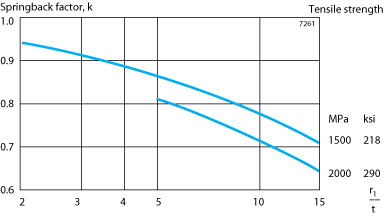
Figure 5. Springback factor. Since the springback also is dependent on the bending method, the tool design, the setting of the press and other factors, the final choice of tool angle and punch radius must be made on the basis of practical trials.
Table 6 below shows average values for the least bending radius, r min . These figures refer to strip with a nominal tensile strength as per tables 4 and 5. The bending tests were carried out according to Swedish Standard SS 11 26 26 method 3, i.e. in a 90° veer block with a 25 mm (1 in.) die opening, the blanked test pieces being 35 mm (1.38 in.) wide and turned so that their burr edge was facing inwards in the bend.
Mechanical properties (nominal value)
| Thickness mm |
Alleima® 7C27Mo2 | Alleima® 13C26 | Alleima® 6C27 |
|---|---|---|---|
| Tensile strength Rm, MPa *) |
|||
| 0.03 - 0.50 | 1800 | 1900 | 1600 |
| (0.50) - 1.00 | 1800 | 1800 | 1600 |
| (1.00) - 2.00 | 1700 | - | 1500 |
| (2.00) - 2.50 | - | - | 1500 |
| Proof strength, Rp0.2, MPa | |||
| 0.03 - 0.50 | 1450 | 1550 | 1300 |
| (0.50) - 1.00 | 1450 | 1450 | 1300 |
| (1.00) - 2.00 | 1350 | - | 1200 |
| (2.00) - 2.50 | - | - | 1200 |
| Elastic limit, 0.01%, MPa | |||
| 0.03 - 0.50 | 1250 | 1300 | 1050 |
| (0.50) - 1.00 | 1250 | 1200 | 1050 |
| (1.00) - 2.00 | 1200 | - | 1000 |
| (2.00) - 2.50 | - | - | 1000 |
| Modulus of elasticity, MPa | |||
| 0.03 - 2.50 | 210 000 for all steels |
*) The manufacturing tolerance is ± 100 MPa
| Thickness in. |
Alleima® 7C27Mo2 | Alleima® 13C26 | Alleima® 6C27 |
|---|---|---|---|
| Tensile strength Rm, psi *) | |||
| 0.0012 - 0.0197 | 261000 | 276000 | 232000 |
| (0.0197) - 0.0394 | 261000 | 261000 | 232000 |
| (0.0394) - 0.0787 | 196000 | - | 218000 |
| (0.0787) - 0.0984 | - | - | 218000 |
| Proof strength, Rp0.2, psi | |||
| 0.0012 - 0.0197 | 210000 | 225000 | 189000 |
| (0.0197) - 0.0394 | 210000 | 210000 | 189000 |
| (0.0394) - 0.0787 | 196000 | - | 174000 |
| (0.0787) - 0.0984 | - | - | 174000 |
| Elastic limit 0.01%, psi | |||
| 0.0012 - 0.0197 | 181000 | 189000 | 152000 |
| (0.0197) - 0.0394 | 181000 | 174000 | 152000 |
| (0.0394) - 0.0787 | 174000 | - | 145000 |
| (0.0787) - 0.0984 | - | - | 145000 |
| Modulus of elasticity, psi | |||
| 0.0012 - 0.0984 | 30 500 000 for all steels |
*) The manufacturing tolerance is ± 14 500 psi
Other mechanical properties on request.
Impact energy
Figure 1 shows impact energy as a function of temperature. The figures on which the curves are based are determined in a Schopper miniature testing machine. Specimens have been extracted parallel to the rolling direction, which means impact at right angles to the rolling direction.
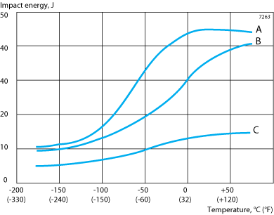
Figure 1.
Impact energy as a function of temperature
A = Alleima® 6C27. Tensile strength 1600 MPa (232000 psi)
B = Alleima® 7C27Mo2. Tensile strength 1800 MPa (261000 psi)
C = Alleima® 13C26. Tensile strength 1900 MPa (276000 psi)
Fatigue strength
The fatigue limit is defined as the stress at which 50% of the test specimens withstand minimum 2 x 10 6 load cycles.
Reversed bending stress (mean stress = 0)
Figure 2 shows a Wöhler S-N curve for Alleima® 7C27Mo2. The corresponding curves for Alleima 13C26 and 6C27 are about 10% lower.
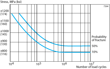
Figure 2. Wöhler S-N curve for Alleima® 7C27Mo2, tensile strength 1800 MPa (261000 psi), max. thickness 1.00 mm (0.0394 in.). Thicker materials have a somewhat lower fatigue strength. The diagram shows that Alleima® 7C27Mo2 with a maximum thickness of 1.00 mm (0.0394 in.) has a fatigue limit of 860 MPa (125000 psi).
Fluctuating tensile stress (minimum stress = 0)
The fatigue limit of Alleima® 7C27Mo2, tensile strength 1800 MPa (261000 psi) and a maximum thickness of 1.00 mm (0.0394 in.) is 650 ± 650 MPa (94000 ± 94000 psi). Strip thicker than 1.00 mm (0.0394 in.) has a fatigue limit which is about 10% lower. The corresponding figures for Alleima® 13C26, and 6C27 are about 10% lower.
Relaxation
The materials have been relaxation tested both at room temperature and at elevated temperature. Figures 3 and 4 show the results obtained with Alleima® 7C27Mo2. The relaxation of Alleima® 13C26 and Alleima® 6C27 is roughly on the same level.
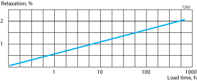
Figure 3.
Relaxation as a function of time at 20 °C (68 °F). Load 1100 MPa (160000 psi). Tensile strength 1700 MPa (247000 psi).
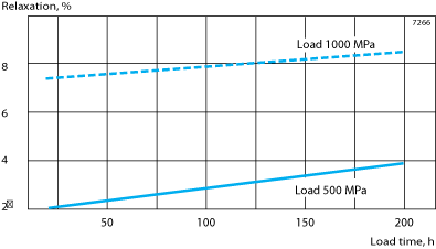
Relaxation as a function of time at 250°C (480°F). Tensile strength 1700 (247000 psi).
Physical properties
The physical properties of a steel are related to a number of factors, including alloying elements, heat treatment and manufacturing route, but the data presented below can generally be used for rough calculations.
| Density | |
|---|---|
| g/cm3 | 7.7 |
| lb/in.3 | 0.27 |
| from 20°C | to 100°C | 10.6 |
|---|---|---|
| to 200°C | 11.1 | |
| to 300°C | 11.4 |
| from 68°F | to 210°F | 5.9 |
|---|---|---|
| to 390°F | 6.2 | |
| to 570°F | 6.3 |
| at | 20°C, W/(m * °C) | 24 |
|---|---|---|
| 68°F, Btu/(ft * h * °F) | 14 |
| mean value for | 50–100°C, J/(kg * °C) | 460 |
|---|---|---|
| 120–210°F, Btu/(lb * °F) | 0.11 |
Blanking
General
Accurate, stable dies and presses are needed to ensure optimum blanking results. A lubricant should be used to reduce tool wear.
Clearance between punch and die
A clearance equaling 4–10% of the strip thickness will give low-level burrs and long tool life and will produce edges with a narrow shear zone and a wide break zone. If the die is tapered, the clearance can be reduced by about half without significantly reducing the life of the die.
The best way of preventing slugs or blanked items riding up with the punch is to fit the punch with a spring-loaded ejector pin. This method is not feasible with slender punches. In cases of this kind, a die without a taper, i.e. with a straight section starting from the edge of the tool, can be used instead. The straight section should be at least 5 times the strip thickness and at least 3 mm (0.118 in.) long.
Tools
Tool grades such as AISI D2 and D4 with a hardness of about HRC 63 are suitable for blanking except in the case of thick material, slender tool sections and small corner radii, for which we recommend AISI M2 high speed steel hardened and tempered to about HRC 63.
AISI M2 for the punch and AISI D4 for the die is often a suitable tool combination. For blanking in long runs we recommend carbide tools, unless the strip is too hard or thick or the shape of the workpiece unsuitable. Further recommendations can be given on request.
The corner radii should be at least 0.25 times the thickness and on no accounts less than 0.25 mm (0.010 in.), while the diameter of the punch should be at least twice the thickness.
Photo-etching
Photo-etching is an alternative to blanking and offers the following important advantages:
- Design freedom
Parts can be designed simply with the best possible function in mind. - Freedom from stresses
Flat parts, free from stresses, can be manufactured. - Lower costs
Inexpensive 'tools' reduce the total cost for small and medium size production series. - Short lead time, high flexibility
'Photo tools' can be manufactured in a very short time. Design changes and modifications are easily done.
Materials
Chromflex ™ is an ideal material for photo-etching. The material is hardened and tempered in a unique vertical furnace. The strip steels are almost entirely free from surface oxides and internal stresses and furthermore have a very good flatness and surface finish combined with excellent mechanical properties. What is more, the structure and hardness of Chromflex™ provide a favorable etching edge.
Laser cutting
This method has advantages similar to photo-etching and is particularly suitable for thick materials. As laser cutting involves heating and melting of the material, it may result in reduced toughness on the cut edge. The toughness is restored by a simple heat treatment. Recommendations can be given on request.
Welding
Generally speaking, martensitic chromium steels are difficult to weld because they harden in air. Welds of adequate functional stability can, however, be obtained under controlled conditions. Resistance welding in the form of butt- and flashwelding is used, for example, in the manufacture of endless strip.
The welding current and upset force are greater than those required for butt- and flashwelding carbon steel. A perfect weld demands careful preparation of the joint, the removal of oxide and other impurities and clean clamps. The welding operation should be followed by tempering, 760-780°C (1400-1435°F) for 45 sec., in order to reduce hardness peaks and homogenize the structure.
For butt welding of thin strip we recommend micro plasma laser or electron beam welding followed by tempering at 600°C (1110°F), 2-3 minutes, or at 650°C (1200°F), 15 sec.
The weld should be cooled to room temperature before the tempering operation. To obtain a perfect weld, accurate joint preparation (straight, even edges) followed by cleaning of the edges, is required. Alleima can assist to develop welding procedures in particular cases.
Disclaimer: Recommendations are for guidance only, and the suitability of a material for a specific application can be confirmed only when we know the actual service conditions. Continuous development may necessitate changes in technical data without notice. This datasheet is only valid for Alleima materials.