Sanmac® 4541 is a titanium-stabilized austenitic chromium-nickel steel with improved machinability
Standards
- ASTM: 321
- UNS: S32100
- EN Number: 1.4541
- W.Nr.: 1.4541
- DIN: X 6 CrNiTi 18 10
Product standards
- EN 10088-3
- ASTM A-314
Suitable for the production of flanges etc. according to ASTM A-182 Grade F321.
Certificates
Status according to EN 10 204/3.1
Chemical composition (nominal) %
| C | Si | Mn | P | S | Cr | Ni | Mo | Others |
|---|---|---|---|---|---|---|---|---|
| 0.03 | 0.6 | 1.8 | ≤0.040 | ≤0.030 | 17.5 | 9.5 | - | Ti>5x(C+N) |
Applications
Sanmac® 4541 is used for a wide range of industrial applications, where steels of type AISI 304/304L have insufficient corrosion resistance.
| Industrial categories | Typical applications |
|---|---|
| Chemical industry | Flanges |
| Food industry | Valves |
| Petrochemical industry | Fittings |
| Pulp and paper industry | Couplings |
| Nuclear industry | Rings |
| Seals | |
| Bolts and nuts | |
| Shafts | |
| Forgings | |
| Discs |
Forms of supply
Sizes and tolerances
Round-cornered square, as well as round billets, are produced in a wide range of sizes according to the following tables. Larger sizes offered on request.
Surface conditions
Square billets
Unground, spot ground or fully ground condition.
Round billets
Peel turned or black condition.
| Size | Tolerance | Length |
|---|---|---|
| mm | mm | m |
| 80 | +/-2 | 4 - 6.3 |
| 100, 114, 126, 140, 150 | +/-3 | 4 - 6.3 |
| 160, 180, 195, 200 | +/-4 | 4 - 6.3 |
| >200 - 350 | +/-5 | 3 - 5.3 |
Sizes and tolerances apply to the rolled/forged condition.
| Size | Tolerance | Length |
|---|---|---|
| mm | mm | m |
| 75 - 200 (5 mm interval) | +/-1 | max 10 |
| >200 - 450 | +/-3 | 3 - 8 |
| Size | Tolerance | Length |
|---|---|---|
| mm | mm | m |
| 77 - 112 (5 mm interval) | +/-2 | max 10 |
| 124, 134 | +/-2 | max 10 |
| 127, 147, 157 | +/-2 | max 10 |
| 142, 152, 163 | +/-2 | max 10 |
| 168, 178, 188 | +/-2 | max 10 |
| 183, 193 | +/-2 | max 10 |
Other products
- Hollow bar (Sanmac®)
Mechanical properties
Testing is performed on separately solution annealed and quenched test pieces. The following figures apply to material in the solution annealed and quenched condition.
At 20°C (68°F)
| Proof strength | Tensile strength | Elong. | Contr. | HB | |
|---|---|---|---|---|---|
| Rp0.2a) | Rp1.0 a) | Rm | Ab) | Z | |
| MPa | MPa | MPa | % | % | |
| ≥210 | ≥245 | 515-700 | ≥40 | ≥50 | ≤215 |
| Proof strength | Tensile strength | Elong. | Contr. | HB | |
|---|---|---|---|---|---|
| Rp0.2a) | Rp1.0 a) | Rm | Ab) | Z | |
| ksi | ksi | ksi | % | % | |
| ≥30.5 | ≥35.5 | 75-101.5 | ≥40 | ≥50 | ≤215 |
1 MPa = 1 N/mm2
a) Rp0.2 and Rp1.0 correspond to 0.2% offset and 1.0% offset yield strengths, respectively.
b) Based on L0 = 5.65 √S0 where L0 is the original gauge length and S0 the original cross-sectional area.
Impact strength
Due to its austenitic microstructure, Sanmac® 4541 has very good impact strength both at room temperature and at cryogenic temperatures.
Tests on bar have demonstrated that the steel fulfils the requirements (60 J (44 ft-lb) at -196oC(-320oF)), according to the European standards EN13445-2(UFPV-2) and EN 10272.
At high temperatures
| Temperature | Proof strength | Tensile strength | |
|---|---|---|---|
| Rp.02 | Rp1.0 | Rm | |
| °C | MPa | MPa | MPa |
| min. | min. | min. | |
| 100 | 175 | 205 | 440 |
| 200 | 155 | 185 | 390 |
| 300 | 135 | 167 | 375 |
| 400 | 125 | 156 | 375 |
| 500 | 119 | 149 | 360 |
| Temperature | Proof strength | Tensile strength | |
|---|---|---|---|
| Rp.02 | Rp1.0 | Rm | |
| °F | ksi | ksi | ksi |
| min. | min. | min. | |
| 200 | 25.4 | 29.7 | 63.8 |
| 400 | 22.5 | 26.8 | 56.6 |
| 600 | 19.6 | 24.2 | 54.4 |
| 800 | 18.1 | 22.5 | 54.4 |
| 1000 | 17.2 | 21.6 | 52.2 |
Machining
General
Sanmac® stands for Sandvik Machinability Concept. In Sanmac® materials, machinability has been improved without jeopardizing properties, such as corrosion resistance and mechanical strength.
Improved machinability is brought about by:
- Optimized non-metallic inclusions
- Optimum chemical composition
- Optimized process and production parameters
Detailed recommendations for the choice of tools and cutting data, for turning, thread cutting, parting/grooving, drilling, milling and sawing, are provided in the brochure S-029-ENG.
Machining chart
The diagram shows the ranges, within which data should be chosen in order to obtain a tool life of 10 minutes minimum, when machining the austenitic Sanmac® 4541. The ranges are limited in the event of low feeds, because of unacceptable chip breaking. In the case of high cutting speeds, plastic deformation is the most dominant cause of failure. When feed increases and the cutting speed falls, edge frittering (chipping) increases significantly. The diagram is applicable for short cutting times. For long, continuous cuts, cutting speeds should be reduced somewhat.
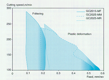 Figure 1. Machining chart for Sanmac 4541.
The lowest recommended cutting speed is determined by the tendency of the material to stick to the insert (built-up edge), although the integrity of insert clamping and the stability of the machine are also of great significance.
It is important to conclude which wear mechanism is active, in order to optimize cutting data with the aid of the diagram.
Turning Sanmac® 4541
Recommended insert and cutting data (starting values)
| Insert Geometry | Grade | Cutting data Feed | Cutting speed |
Application
|
|---|---|---|---|---|
| mm/rev. | m/min | |||
| MF | GC2015 | 0.15 | 240 | Finishing, copy turning |
| MM | GC2025 | 0.25 | 210 | Medium machining |
| MR | GC2025 | 0.30 | 180 | Medium-to-rough machining under less stable conditions |
Drilling Sanmac® 4541
The recommended methods for drilling give the most cost effective results for the respective diameter ranges. When producing holes with diameters larger than 58 mm, short hole drilling is used up to 58 mm, followed by internal turning, up to the desired diameter. Cutting data for internal turning should be chosen in accordance with the turning recommendations. The recommendations for drilling are applicable for a tool life of 30 minutes.
Short hole drilling, diameter 12.7 - 58 mm
Coromant U-drill, R416.2
| Insert Geometry | Grade | Cutting data, Feed | Cutting speed |
|---|---|---|---|
| mm/rev. | m/min | ||
| -53 | Central insert GC1020 | - | - |
| -53 | Peripheral insert GC1020* | 0.04-0.18 | 150 |
| -53 | Peripheral insert GC3040** | 0.04-0.18 | 200 |
* GC1120 for diameters below 17.5 mm
** stable conditions, otherwise use GC1020 and cutting speed 180 m/min
Drilling with Alleima Coromant Delta C drill, diameter 3 - 12.7 mm
Code R415.5. Grade GC1220
(diameter range 3 - 20 mm)
| Cutting data, Feed* | Cutting speed |
|---|---|
| mm/rev. | m/min |
| 0.08-0.22 | 40 |
* The lower feed value should be selected for smaller diameters.
Drilling with high speed steel (HSS) drill
(diameter 1-3 mm)
| Cutting data, Feed* | Cutting speed** |
|---|---|
| mm/rev. | m/min |
| 0.03-0.09 | 8-15 |
* The lower feed value should be selected for smaller diameters
** The higher cutting speed should be selected for coated drills
Milling Sanmac® 4541
Use of optimum cutting data means that milling can be carried out at cutting speeds above those where there is a risk of built-up edge formation. Dry milling results in long tool life. If coolant is needed (e.g. when the surface cannot be reached in the dry condition) the cutting speed must be reduced by approximately 40-60% to prevent tool wear due to increased thermal load on the inserts.
| Roughing Geometry/Grade | Cutting speed | Finishing Geometry/Grade | Cutting speed |
|---|---|---|---|
| m/min | m/min | ||
| MM-2030 | 180 | ML-2030 | 225 |
1) Starting values for dry machining.
Threading Sanmac® 4541
Indexable inserts can be used for external thread cutting of all diameters. Threading with screw-cutting dies or die heads is economical only for small diameters. For internal threading with short and normal cutting lengths, thread cutting with indexable inserts is recommended above a hole diameter of 12 mm. For long cutting lengths, thread cutting with indexable inserts is recommended for hole diameters above 20 mm.
Thread turning
Due to the tendency of austenitic materials to work harden, radial infeed is recommended. A generous flow of cutting fluid should also be used, partly to obtain a reliable process and partly to guide the chip. The recommendations apply to a tool life of 30 minutes.
| Insert Geometry | Grade | Cutting speed |
|---|---|---|
| m/min | ||
| All-round | GC1020 | 150 |
Thread tapping
Compared with uncoated threading taps, coated threading taps can improve productivity by up to 100%. For the advantages of coated threading taps to be realized, a generous flow of cooling fluid must be used. The recommendations apply to a tool life of 30 minutes.
| Cutting speed |
|---|
| m/min |
| 4-15 |
The higher range of cutting data should be chosen for coated threading taps
Sawing of Sanmac® 4541
Cutting with bandsaws or cold saws gives the best cutting economy. If the demand for surface smoothness is great, circular sawing is preferable.
Band sawing gives high productivity, is flexible and incurs low investment costs.
When band sawing Sanmac® 4541, the Sandflex Cobra type 3851 bimetallic bandsaw blades, which is available from Bahco Group (formerly Sandvik Saws and Tools), is recommended.
Tooth spacing should be selected according to the dimensions of the material to be cut, and stated in TPI (the number of teeth per in.). The TPI should be reduced for thicker dimensions. For a bar dimension of D = 150 mm, 2/3 TPI or 1/2 TPI is recommended.
| Cutting speed |
|---|
| m/min |
| 45-50 |
Feed is regulated to obtain a good chip form.
Disclaimer: Recommendations are for guidance only, and the suitability of a material for a specific application can be confirmed only when we know the actual service conditions. Continuous development may necessitate changes in technical data without notice. This datasheet is only valid for Alleima materials.