Alleima® 20C is a hardened and tempered carbon steel characterized by good properties in respect of:
- Fatigue strength and wear resistance
- Hardness combined with ductility
- Dimensional tolerances
- Surface and edge finishes
- Shape
The material also has good blanking and forming properties, retaining the shape of the parts after the blanking operation.
Standards
- ASTM: 1095
- EN Number: 1.1274
Chemical composition (nominal)
| C | Si | Mn |
|---|---|---|
| 1.00 | 0.25 | 0.45 |
Applications
- Washers in automatic transmissions
- Lapping carriers and cutter blades for the semiconductor industry
- Coater and scraper blades for the pulp and paper industry
- Springs in general
- Doctor blades for printing processes
- Knives
- Trowels
Dimensions
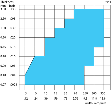
Alleima® 20C is available in a wide range of sizes. The following chart indicates the approximate standard size range.

Figure 1: Standard size range
Finishes and forms of supply
The strip steel can be supplied in coils or lengths with various edges and surfaces.
Blanking and bending
Blanking
In order to achieve optimal blanking results tools and presses must be accurate and stable in dealing with hardened and tempered strip. A lubricant is recommended to minimize tool wear.

Clearance between punch and die
A radial clearance of 4–10% of the strip thickness is recommended. This will give low burr height in combination with long tool life and a sheared edge with a narrow shear zone and a wide break zone.
Tools
Tool steels of type AISI D2 or D4 with hardness about 63 HRC can be used except where thick gauges, slender tool sections and small corner radii are involved. In that case we recommend high-speed steel, type AISI M2 hardened and tempered to about 63 HRC.
Carbide tools are recommended for blanking in very long runs, unless the strip is too hard and thick or the shape of the items is unsuitable. More detailed recommendations will be furnished on request. The corner radii should be min. 0.25 x the strip thickness, but not smaller than 0.25 mm (0.010 in.), and the diameter of the punch not smaller than 2 x the strip thickness.
The risk of the hole slug or the blanked item being carried along with the punch on its return stroke can be lessened by using a die without a taper, i.e. with a straight section starting from the edge of the tool. The straight section should be at least 5 x the strip thickness or at least 3 mm (0.118 in.) in length.
Bending
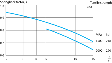
Table 6 shows average values for the least bending radius, r min . These figures refer to strip with a nominal tensile strength as per table 5. The bending tests were carried out according to Swedish Standard SS 11 26 26 method 3, i.e.in a 90° vee block with a 25 mm (1 in.) die opening, the blanked test pieces being 35 mm (1.38 in.) wide and turned so that their burr edge was facing inwards in the bend.


Mechanical properties
Nominal values at 20°C.
| Thickness | Tensile strength | Proof strength | |||
|---|---|---|---|---|---|
| mm | in. | MPa | psi | MPa | psi |
| <0.125 | <.005 | 2100 | 304 500 | 1900 | 276 000 |
| 0.125-<0.175 | .005-<.007 | 2050 | 297 250 | 1850 | 268 000 |
| 0.175-<0.225 | .007-<.009 | 2000 | 290 000 | 1800 | 261 000 |
| 0.225-<0.275 | .009-<.011 | 1950 | 282 750 | 1750 | 254 000 |
| 0.275-<0.375 | .011-<.015 | 1900 | 275 500 | 1700 | 247 000 |
| 0.375-<0.425 | .015-<.017 | 1850 | 268 250 | 1650 | 239 000 |
| 0.425-<0.475 | .017-<.019 | 1800 | 261 000 | 1600 | 232 000 |
| 0.475-<0.625 | .019-<.025 | 1750 | 253 750 | 1600 | 232 000 |
| 0.625-<0.825 | .025-<.032 | 1700 | 246 500 | 1550 | 225 000 |
| 0.825-<1.000 | .032-<.039 | 1650 | 239 250 | 1500 | 218 000 |
| 1.000-<1.575 | .039-<.062 | 1600 | 232 000 | 1450 | 210 000 |
| 1.575-<2.500 | .062-<.098 | 1600 | 232 000 | 1450 | 210 000 |
| 2.500-<3.500 | .098-<.118 | 1600 | 232 000 | 1450 | 210 000 |
Physical properties
The physical properties of a steel are related to a number of factors, including alloying elements, heat treatment and manufacturing route, but the data presented below can generally be used for rough calculations.
Density, g/cm3: 7.85
lb/in3: 0.28
Thermal expansion per °C, x10 –6:
from 20°C to 100°C: 10.4
to 200°C: 11.6
to 300°C: 12.4
per °F, x 10 –6 ,
from 68°F to 210°F: 5.8
to 390°F: 6.4
to 570°F: 6.9
Thermal conductivity
at 20°C, W/(m · °C): 49
68°F, Btu/(ft · h · °F): 28
Tolerances
In the standard finish, the tolerances is symmetrical, half above and half below the nominal size. Other tolerances can be discussed. The tolerances are based on the Swedish Standards SS 21 21 10 and 21 21 11 respectively.
Thickness tolerance
The standard tolerance is T1 according to table 3. Closer tolerances can be agreed upon.
Width tolerance
The standard tolerance is B1 according to table 4. Closer tolerances can be agreed upon.
| Strip thickness | Thickness tolerance | ||
|---|---|---|---|
| mm | in. | mm± | in.± |
| <0.063 | <0.0024 | 0.005 | 0.00020 |
| <0.100 | <0.0039 | 0.006 | 0.00024 |
| <0.125 | <0.0049 | 0.007 | 0.00028 |
| <0.160 | <0.0063 | 0.009 | 0.00035 |
| <0.200 | <0.0079 | 0.010 | 0.00039 |
| <0.250 | <0.0098 | 0.011 | 0.00043 |
| <0.315 | <0.0124 | 0.013 | 0.00051 |
| <0.400 | <0.0158 | 0.015 | 0.00059 |
| <0.500 | <0.0197 | 0.017 | 0.00067 |
| <0.630 | <0.0248 | 0.020 | 0.00079 |
| <0.800 | <0.0315 | 0.023 | 0.00091 |
| <1.000 | <0.0394 | 0.027 | 0.00106 |
| <1.250 | <0.0492 | 0.034 | 0.00134 |
| <1.600 | <0.0630 | 0.039 | 0.00154 |
| <2.000 | <0.0787 | 0.046 | 0.00181 |
| <2.500 | <0.0984 | 0.050 | 0.00197 |
| <3.150 | <0.1240 | 0.056 | 0.00220 |
| <3.500 | <0.1380 | 0.063 | 0.00248 |
Table 4. Width tolerances, B1
| Thickness | Width | ||||||||||
|---|---|---|---|---|---|---|---|---|---|---|---|
| mm | in. | mm | in. | mm | in. | mm | in. | mm | in. | mm | in. |
| <20 | <0.70 | <50 | <1.97 | <125 | <4.92 | <250 | <9.84 | <350 | <13.8 | ||
| tolerance | |||||||||||
| mm± | in. ± | mm± | in.± | mm± | in.± | mm± | in.± | mm± | in.± | ||
| <0.25 | <0.098 | 0.07 | 0.0028 | 0.10 | 0.0039 | 0.15 | 0.0059 | 0.20 | 0.0079 | 0.30 | 0.0118 |
| <0.50 | <0.020 | 0.10 | 0.0039 | 0.15 | 0.0059 | 0.20 | 0.0079 | 0.25 | 0.0098 | 0.35 | 0.0138 |
| <1.00 | <0.039 | 0.15 | 0.0059 | 0.20 | 0.0079 | 0.25 | 0.0098 | 0.30 | 0.0118 | 0.40 | 0.0157 |
| <1.60 | <0.063 | 0.20 | 0.0079 | 0.25 | 0.0098 | 0.30 | 0.0118 | 0.35 | 0.0138 | 0.45 | 0.0177 |
| <2.00 | <0.079 | 0.25 | 0.0098 | 0.30 | 0.0118 | 0.35 | 0.0138 | 0.40 | 0.0157 | 0.50 | 0.0197 |
| <2.50 | <0.098 | 0.35 | 0.0138 | 0.35 | 0.0138 | 0.40 | 0.0157 | 0.45 | 0.0177 | 0.55 | 0.0217 |
| <4.00 | <0.158 | – | – | 0.40 | 0.0157 | 0.45 | 0.0177 | 0.50 | 0.0197 | 0.60 | 0.0236 |
Disclaimer: Recommendations are for guidance only, and the suitability of a material for a specific application can be confirmed only when we know the actual service conditions. Continuous development may necessitate changes in technical data without notice. This datasheet is only valid for Alleima materials.